2026.03.28
A New Solution for Intelligent Driving Data Storage: In-Depth Analysis of Hard Drive Hot-Swapping and PCIe Expansion Card Technology
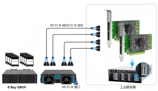
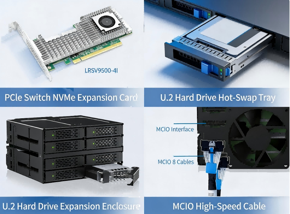
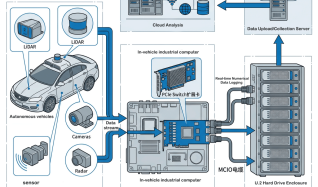
Abstract: With the rapid iteration of intelligent driving technologies, the collection and storage of road-test data have become a critical bottleneck hindering industry development. This paper provides an in-depth analysis of storage solutions based on PCIe switch hard-drive expansion cards, U.2 expansion cards, and M.2 expansion cards. It focuses on how SSD hot-swapping technology enables seamless disk replacement without interrupting operations, thereby helping providers of end-to-end autonomous driving solutions build efficient data infrastructure.
View details